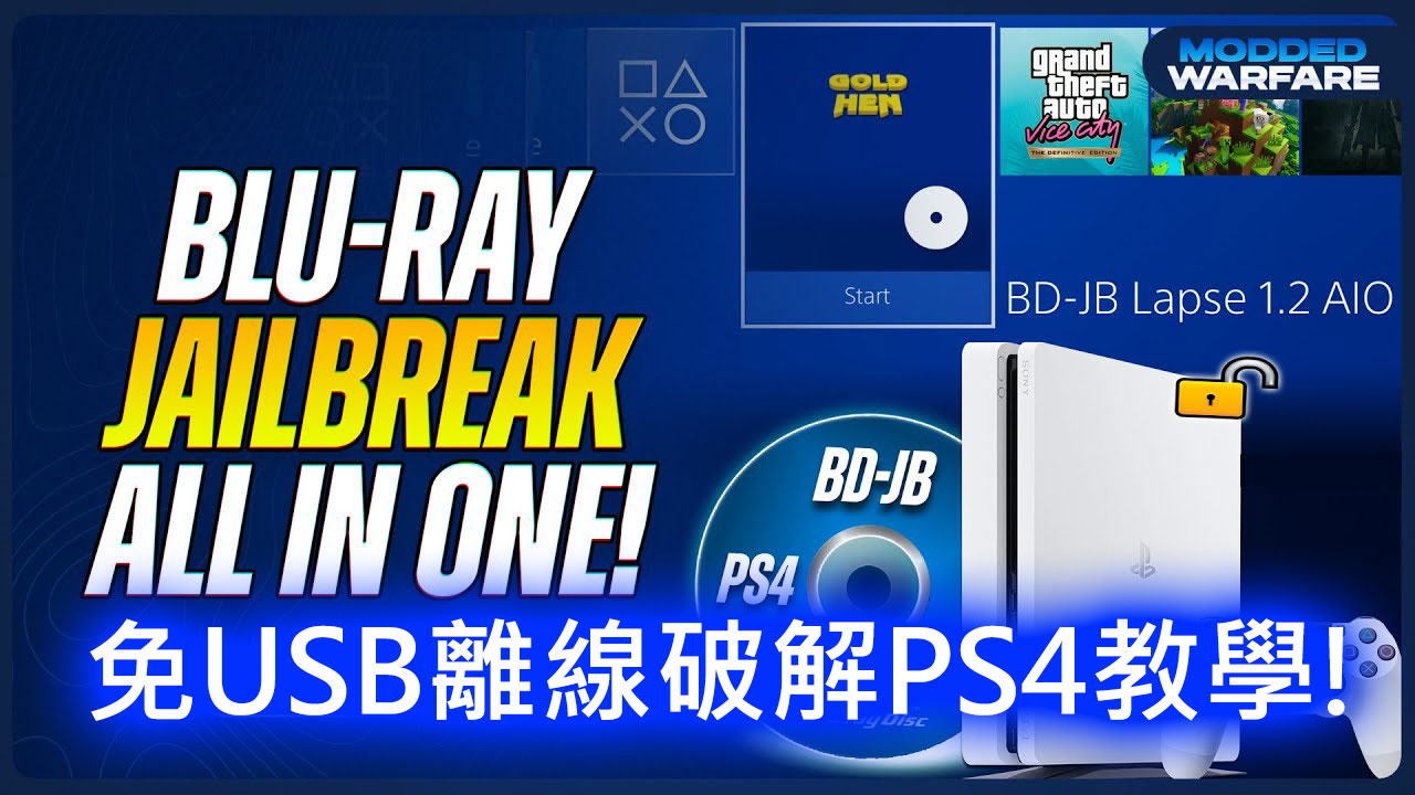
這是一部最新的破解教學影片,教你如何用光碟直接破解,不再需要用USB了,而且支援軔體版本很多,雖然每次開機都要跑一次(還沒辦法固化),但已經是非常簡單的破解法了,期待不久的將來可以有固化的突破。
玩硬體
跟懷舊遊戲相關的硬體,都歸類在此,通常也會同時歸類在玩改機、玩模擬器或是玩週邊,例如樹莓派、開源掌機等等
Sega Saturn的救贖-Saroo燒錄卡深度解析與玩家指南
Sega Saturn,這款讓無數玩家無法忘懷的經典主機,在現代雖已退居歷史舞台,但其上誕生的許多經典遊戲仍無法被取代。然而,隨著實體遊戲光碟越來越稀有、價格水漲船高,加上主機光碟機老化,再次重溫這些懷舊之作對許多玩家來說變得困難重重。
就在這時,SAROO燒錄卡的問世為玩家提供了一種既經濟又便利的解決方案。這款燒錄卡不僅讓你的Sega Saturn無痛重生,還簡化了運行遊戲的方式(早先的Fenirr需要改機,還要對不同型號的針腳)。同時,它兼具便利性與性價比,成為復古玩家口中不可或缺的神器。本篇文章將深入介紹SAROO燒錄卡,包括其功能、安裝方法、使用技巧以及玩家社群分享的經驗。
Analogue釋出2024年的N64新主機-Analogue 3D
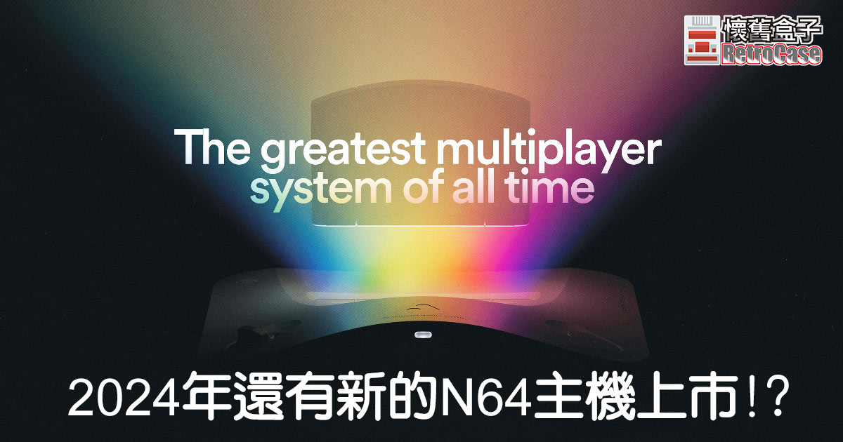
2024年10月21號,Analogue將開賣已經公告兩年的FPGA硬體模擬N64主機 – Analogue 3D,官網價格為$250美金。
以下是簡單的主機介紹:

圖片來源: Analogue
5 Pin 及8 Pin訊號線腳位定義
在論壇逛到的資料,是幾款接頭很像的主機腳位圖示,分別有:
- Commodore 64
- Atari 800
- TI99
- Sega Genesis/Megadrive
廢話不多說,直接上圖

原文連結
https://forums.atariage.com/topic/291224-audiovideo-5-or-8-pin-din-for-cats-commodoreatariti99sega
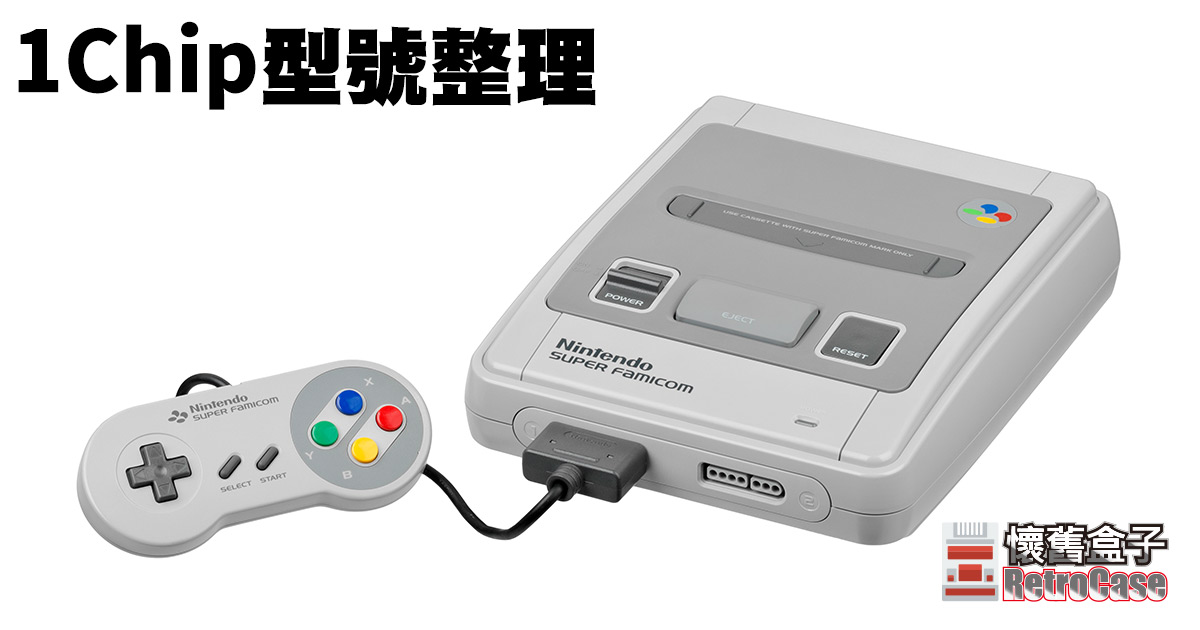
超級任天堂的1Chip型號整理
這裡會把網路上找來的相關資訊都整理在一起,不定期更新,如果你手上也有1Chip機型,歡迎評論區留下你的機身序號!
什麼是1Chip?
1990年發售的超級任天堂,以下簡稱超任,可說是任天堂有史以來最成功的家用遊戲機之一,總共發行了4900萬台,在16位元世代中傲視當時所有遊戲主機(北美於1991年發售、歐洲於1992年發售),一直到2003年才正式終止這部主機的生命週期。
期間任天堂內部也不斷地給這台主機進行各種改進開發,因此也存在著各種不同型號的機板,例如最早的超任是獨立音效處理晶片,中期機型整合音效之後以節省成本。再往後期為了進一步節省成本,把影像(PPU)與處理器晶片(CPU)再整合為一,就是我們要找的1Chip機型,由於整合後的晶片,在處理影像與聲音時因為沒有經過多單元處理再整合成輸出的步驟,少了許多電磁干擾因素,因此1Chip的畫質、音質被認為是表現更好的機型。
而到後超任晚年,任天堂再推出SFC Jr.,也就是徹底COST DOWN超任版本之後,雖然這部機型在當時乏人問津,但這版本是全面搭載1Chip最後期的晶片,畫質達到最高級表現,再加上發行量少,現在成了收藏圈的寶物,價格居高不下(但也不至於到天價)。
型號分別
即使是1Chip機型,也存在著三種版本,從機板上就能看到,分別是1Chip-01、1Chip-02、1Chip-03,其中又以1Chip-03最少,畫質最好,價格也最貴。這是國外網站RetroRGB放出來的畫面比較:
官方懷舊機改機指南整理
從任天堂的Famicom Classic開始,敲響了這波懷舊風,各家主機大廠紛紛投入懷舊小機機的行列,這種用軟體模擬的機器,就像樹莓派一樣,都可以透過軟體方式進行破解,塞入ROM讓機器執行模擬器,甚至灌入不同模擬器讓小超任跑N64、小PS跑紅白機等玩法,以下收集一些改機指南站點,讓玩家有個方向可以依循:
ModMyClassic https://modmyclassic.com/

[備份] 各主機Scart輸出RGB訊號腳位圖
這是從國外找來的資料,我覺得滿重要的,為避免來源網站突然消失,這邊做個備份,有需要還是請到原網站查看,點我前往。
I found it on a forum and think it’s valuable data, just in case it disappear suddenly, I decided to make a copy, not to clone in purpose. If I violate your copyright please inform me and I will delete the post ASAP.


For some unknown reason the RGB output circuits differs between the NTSC and PAL consoles. As a result the cables are different too (though I somehow doubt Nintendo had any intention of releasing a SCART lead for the NTSC SNES).


Nintendo are up to their old tricks again. The PAL console outputs RGB but not s-video and the NTSC model outputs s-video but not RGB. Therefore this cable will only work on a PAL Gamecube. However, it is possible to get RGB from an NTSC Gamecube by modifying the official component video cable. Here are some guides to the procedure:
How to make NGC’s RGB(VGA) Cable [link fixed]
RARusk’s Nintendo GameCube Component Video Cable RGB Modification [link fixed]
MMMonkey’s NTSC Game Cube RGB Cable

Like the Gamecube, RGB video is only available from the PAL Wii.

Sony Playstation/Playstation 2

RGB output circuit: signal comes from a CXA1645 and a through a 75 ohm resistor.
2021.9.29補充:有網友實測之後發現PS2的腳位圖有誤,SCART的PIN8(+5V)跑到PIN2,而原指左聲道(PIN2)其實是在PIN6,特此紀錄,將來有機會再實際測試看看,感謝網友Sean Tang!


and finaly, the Resources
Game Station X – Game console pinouts & modifications
Home video games with RGB monitors – interesting…. [japanese]
Deathskull Laboratories – game console info
BlueTech – game console modifications and other creations
mmmonkey’s console modifications – modifications/fixes with lots of photos
Data sheets in PDF format for:
CXA1145 – [japanese]
ES71145 – CXA1145 compatible
CXA1645
MB3514 – CXA1145 compatible (with Y/C driver output)
KA2195D – CXA1645 compatible (with no Y/C output), may be mistaken as SKA2195D